Simulation 101 with Fusion 360
Fusion 360 has integrated the simulation capabilities that include static stress, thermal and modal analysis. Simulation, also known as Finite Element Analysis allows you to carry out better designs quickly. This function allows you to foresee the behaviour of the product, test your creative ideas and optimise designs in the early stages of the design and engineering process. “By integrating simulation directly within the design and engineering workflow, users can not only build more viable parts with fewer iterations, but they can also develop intuition and expertise to reach validation more quickly.” said Kevin Schneider, director of Fusion 360 at Autodesk.
We normally depend on our senior engineers to come up with solutions that are new and better. You need extensive experience to be able to come up with suggestions that would be efficient. The simulation functionality is changing that. The simulation tool is so fast and accurate that it helps you understand the functionality of a design better and gives ways in which to improve it.
Why do we use Simulation?
Simulation helps you validate your design decisions, it will analyse the strength of your design – will it handle the load? Is it quality or have you under-designed? It will predict the performance of your designs; this analysis helps reduce the risk of failure as it predicts how your design will response under favourable and unfavourable conditions.
As a designer, it is important to know early in the process whether your design will be successful or not, or whether your product will function as you intend it to. You need to know you’re making the right design decisions without having to build multiple physical prototypes first. Simulation enables these critical engineering decisions to be made earlier in the design process.
As mentioned; there are four different types of studies in Simulation which include Static stress, Modal frequencies, Thermal and Thermal Stress. In this blog, we will focus on the static stress simulation.
Static Stress Simulation
Why static stress?
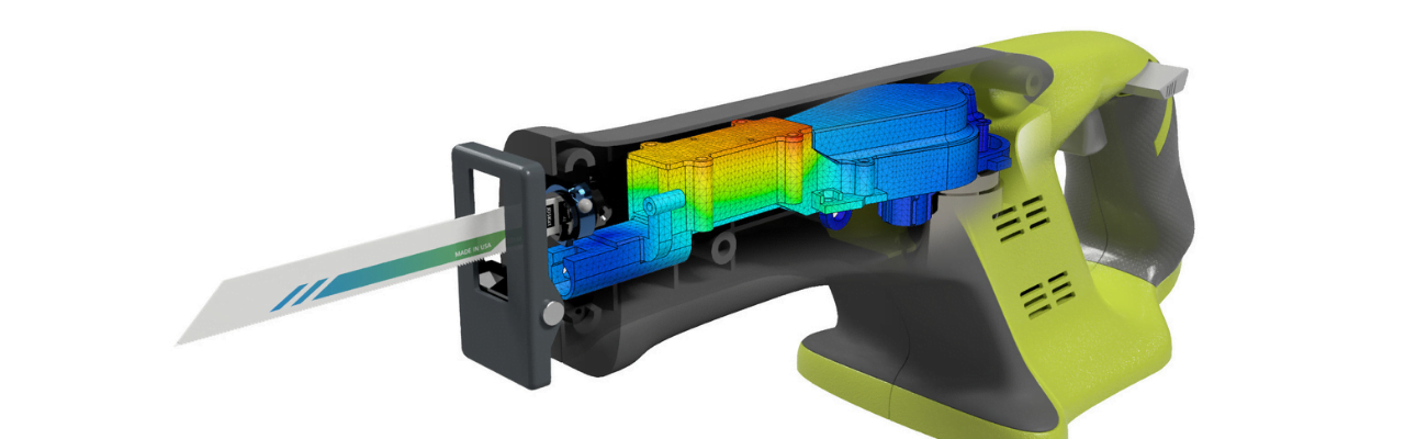
When you design mechanical objects, you want them to be sturdy enough. If you make an infirm object it will break and if you make the objects too sturdy it will be bigger, heavier and often more expensive. By simulating static stress, you can strip down unnecessary parts and reinforce weak points before sending your part to production, making your part strong where you need it to be and at the same time smaller, lighter and cheaper.
When simulating Static Stress in Fusion 360 first thing you need to do is decide what bodies or components in your assembly you want to be part of the simulation study. You can do so by checking or unchecking in your browser which components you wish to include. Once you have done that you can choose what material the different bodies will be simulated as. Following that your simulation will need at least one constraint as without one it would be like trying to apply force on a floating object.
Application of loads and constraints
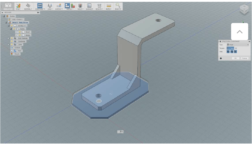
setting a fixed structural constraint on the bottom of the base plate.
There are different types of constraints that you can apply to your object. A fixed constraint is the most basic type of constraint where you select one or more face, edge or vertex that will stick in one rigid place no matter what. The pinned constraint on the other hand, is applied on cylindrical faces. As with the axes in the fixed constrained type, there are three types of pinned constraints that can be switched on and off. One, the radial constraint; this will prevent the cylinder from moving as if you have a pin in the hole. Two, the axial constraint; this will prevent the cylinder from sliding along the pin and three, the tangential constraint, this type prevents the cylinder from rotating.
Once you have set your constraints and all is in order, you can start applying load or force to different parts of your component, either on the vertices, edges, surfaces or lines. Loads help simulate the conditions that a design can come across. There are different load types and load directions that can be applied to your faces. The loads also give us the ability to define a radius of the load as well as check display to see what’s being bonded and what’s fixed.
Contacts
The contact function is only necessary if you have more than one body in your simulation. It defines how bodies should behave relative to each other. Contacts are also constraints but only relative between bodies. This contact constraint function defines how bodies should be made. There are four types of contacts that can be used; bonded, separation (no sliding), sliding (no separation) and separation & sliding. The display tab shows if it is fully constrained or not. Green representing a fully fixed part, cyan showing potentially fixed, yellow means partially fixed and red represents a free, non-fixed part.
Once the contact and load functions are complete, the solve traffic light icon on the toolbar should be green and if so go ahead and let the simulation run. You will then get a comprehensible message describing the success or errors of your set up. After a successful solve, you will then be able to examine different types of results. The safety factor, stress (a quantity of how much pressure a particle exerts on a neighbouring particle), displacement (how much body has deformed relative to its original state), strain (a measure of deformation in the material) and contact (pressure between two contact surfaces). Another item on results is the animating functionality, it helps you see how force is affecting your model.
It’s important to simulate for a reason, and this is not necessarily as easy as it might seem. Look out for our webinar that also focuses on basic simulation in Fusion 360. Some of the takeaways from the webinar include being able to set up different analysis, improving your designs and cloud solving. Knowing what to look for and tweaking your model after examining the simulation results to optimise the design takes some practice and knowledge to master.
Baker Baynes is a Gold Partner of Autodesk products in South Africa and the only Simulation Specialised partner. For more information request a meeting with our Simulation Specialist.


0 Comments