Autodesk
Fusion 360
Fusion 360 Core & Extensions
Unify design, engineering, electronics, and manufacturing with Fusion 360 – Integrated CAD, CAM, CAE, and PCB software
About Fusion 360
- Design and engineer products how you want to ensure aesthetics, form, fit, and function
- Engineer, design, and create anything with comprehensive electronics and PCB design tools
- Save time and money and get quality parts out the door faster
Top Fusion 360 Features
Extend your Platform
Eliminate disconnected tools and wasteful overhead by optimizing workflows on one platform.
Simplify your Manufacturing Process
Reduce time to market with automated operations and optimized workflows across teams.
Make Innovating Easier
Cut non-value-add processes and enhance collaboration for easier development of products.
Interactive Assemblies
Detailed visualizations of complex products with exploded views and animations.
Push-button SPICE Simulation
Easy SPICE (Simulation Program with Integrated Circuit Emphasis) Ssetup.
Flexible 3D Modeling and Design
Use direct, surface, parametric, mesh, or freeform modeling.
Sheet Metal Part Creation
Design and engineer products to ensure aesthetics, form, fit and function.
Integrated CAD and CAM
Additive manufacturing, 2 & 3-axis, 3+2, 4 & 5-axis milling and more.
What does Fusion 360 Include?
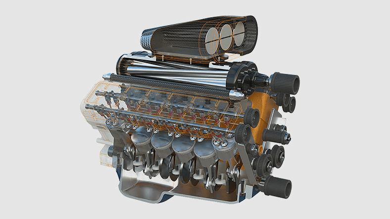
Flexible 3D CAD
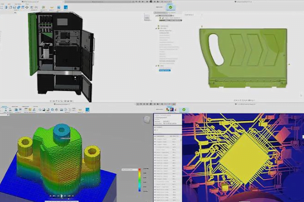
Fusion 360 enables you to explore many iterations quickly with easy-to-use CAD software.
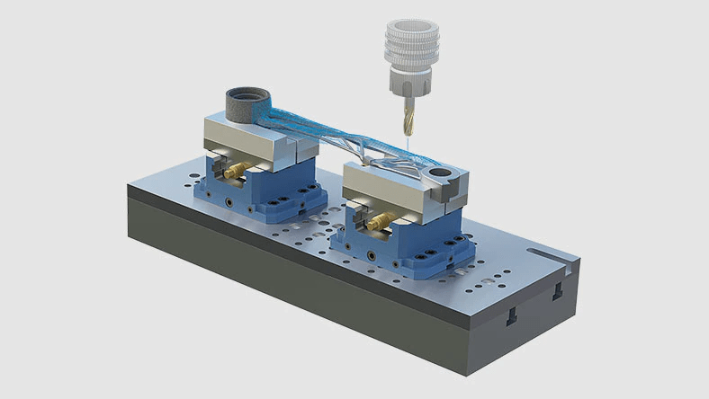
Integrated CAD/CAM
Produce high-quality CNC machined parts, and additively manufacture builds using FFF or PBF for metal 3D printing.
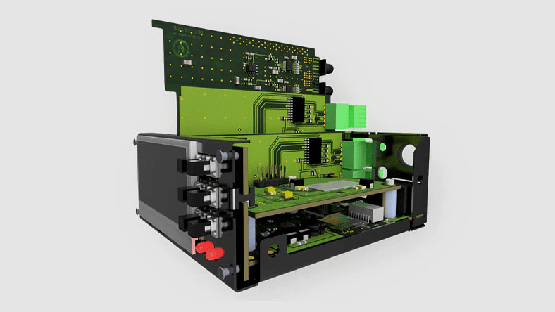
Unified PCB design
Gain all the advantages of a full-featured schematic capture, electronics design, and mechanical CAD with Fusion 360.
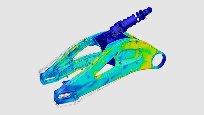
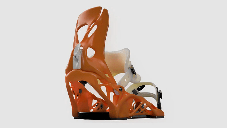
Flexible 3D CAD
Fusion 360 enables you to explore many iterations quickly with easy-to-use CAD software.
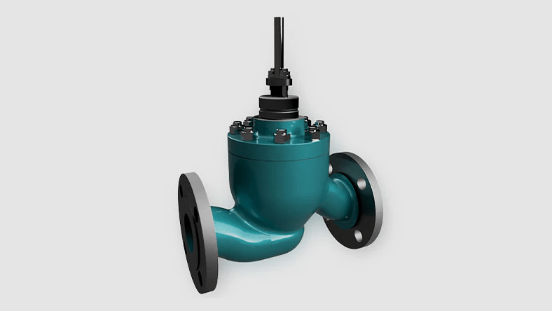
Integrated CAD/CAM
Produce high-quality CNC machined parts, and additively manufacture builds using FFF or PBF for metal 3D printing.
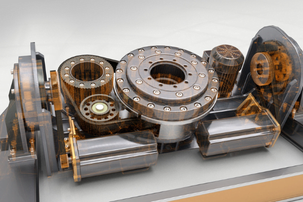
Unified PCB design
Gain all the advantages of a full-featured schematic capture, electronics design, and mechanical CAD with Fusion 360.
Fusion 360 Extensions
Add extensions with flexible subscription options to fit your project budget & project need. These extensions need to be added to Fusion 360.
Fusion 360
View Features
- Design and communicate your solution
- Engineer and simulate your designs (Nastran, Generative design, Tolerance analysis)
- Visualize your designs (Rendered images/CGI/VR)
- Create manufacturing data (BOM, Drawings, Nesting + CAM)
- Worldwide access to CADLearning content for unlimited users via web, mobile and CADLearning plugin
- Build custom playlists based on quiz and search results
- Unlimited storage for custom learning content
- Reporting and Analytics
- Detailed user activity reports for video views and assessment attempts
- Admin dashboards and automated reports
- Data feeds for existing client reporting platforms and tools (ERP, Tableau, Domo etc.)
- Two one-hour administrator training sessions, Portal Administration Overview: includes user management, customizing your learning environment and reporting
- Advanced Portal Administration: includes content reconfiguration, custom content, and advanced reporting
- First-class support for administrators and users via support.cadlearning.com
- Monthly end-user basics webinars
- CADLearning User Engagement: toolkit to help build awareness and grow usage of your CADLearning portal
Simulation Extension
View Features
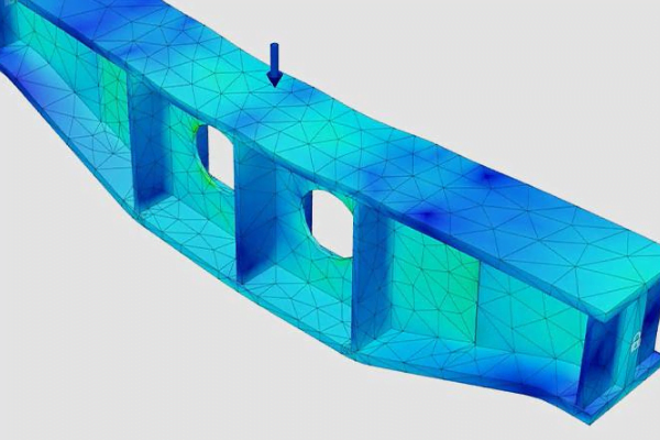
- Static Stress -Inspect a range of load conditions and the resultant stress, strain, and deformation results analyzed to determine the likelihood of failure of the design.
- Modal Frequencies – Inspect the effects of natural free-vibration on your part or assembly to help you fine-tune your design.
- Thermal Steady State -Trace heat transfer across your part or assembly to understand if your part may fail based on the maximum critical temperature of a component.
- Thermal Stress -Simulate temperature-induced stresses caused by temperature gradients in the model and varying thermal expansion characteristics of the materials.
- Shape Optimization – Achieve light weight design goals by identifying material can be removed from your design, while still achieving allowable stress and displacement objectives.
- Nonlinear Static Stress – Explore large deformation, motion, contact and load changes, and nonlinear material behavior during an event or an incremental change in loads.
- Event Simulation – Predict how time-dependent forces influence design performance.
- Structural Buckling – Determine the critical buckling multiplier and modal buckling shape from a compression load applied to your structural component to develop a support or stiffening structure to prevent structure failure due to buckling.
- Injection Molding Simulation – Identify how your part design influences part manufacturability and part quality for plastic injection molded parts through guided results to get an aesthetically acceptable part that will perform as intended.
Generative Design Extension
View Features
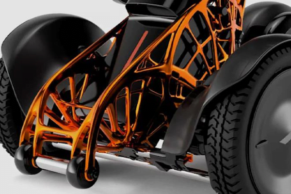
- Multi-Objective Design Exploration – AI-powered algorithms produce multiple design iterations optimized tom meet your design objectives, including functional, physical, performance, and chosen manufacturing method, automatically using a single problem definition. Easily designate specific design objectives, including functional, physical, manufacturing method, and performance factors, for AI-powered algorithms to automatically generate various design iterations with a single solve.
- Manufacturing aware – Influence designs through manufacturing process considerations. Supported processes include additive manufacturing, 3 & 5 axis milling, 2.5 axis milling, 2 axis cutting, and die casting.
- Edit-able CAD Design Results -Generative design outcome geometry is automatically reconstructed to produce native CAD features, fostering easy refinement capabilities for finalizing product designs.
- Manufacturing Cost Insights – Effortlessly visualize and filter through manufacturing costs by comparing materials, part designs, part volumes, performance criteria, and manufacturing methods, to identify the “just right” design.
Machining Extension
View Features
- Drilling:
- Hole drilling (3-axis)
Access a range of 3-axis toolpaths and workflows to efficiently machine holes in your 2D and 3D CAD models.
Includes template driven drilling, thread milling, tapping, boring and more.
- Includes automatic feature recognition, machining templates, multi-axis drilling, tapping, thread milling, boring, and more.
Milling:
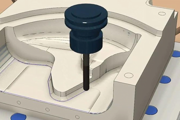
- 2D and 2.5-axis milling
Create toolpaths and NC code to produce 2D features using CNC mills, routers, water jet cutters, laser cutters, plasma cutters.
Includes 2D adaptive clearing, pocket machining, face milling, slot machining, contouring, and more.
- 3-axis milling
- Access 3-axis strategies to effectively rough and finish machine more complex parts containing free-form 3D geometry.
Includes 3D adaptive clearing, flat, parallel, scallop, contour, flow machining, and more .
3+1 and 3+2 axis positional milling
Includes 4-axis wrapping of 2D toolpaths, align tool axis to view/surface normal, interactive tool axis tilt and turn.
- Machine simulation
Includes access to a free library of 3D machine models, machine/toolpath animation, and more .
Automated entire part machining (3-axis and multi-axis) . Includes 3-axis steep and shallow machining.
- 4- and 5-axis simultaneous milling. Includes 4-axis rotary, 5-axis steep & shallow, swarf, multi-axis contour, multi-axis flow, and more.
- Multi-axis collision avoidance. Includes 4- and 5-axis collision avoidance, advanced tool axis smoothing, tool axis tilting limits, and more.
Turning:
- 2-axis turning . Includes face, profile (rough and finish), groove, thread, chamfer, part-off, part handling sub-spindles, and more.
- Turn-mill machining
Modifications:
- Toolpath modifications – Limit/split/delete sections
- Toolpath modifications – Replace tool
Inspection & Part Alignment:
- Work Coordinate System (WCS) setup probing
- Manual inspection
- Geometry probing
- Surface inspection
- Part alignment
Posts:
Post-processing of NC code
Nesting & Fabrication Extension
View Features
Parts:
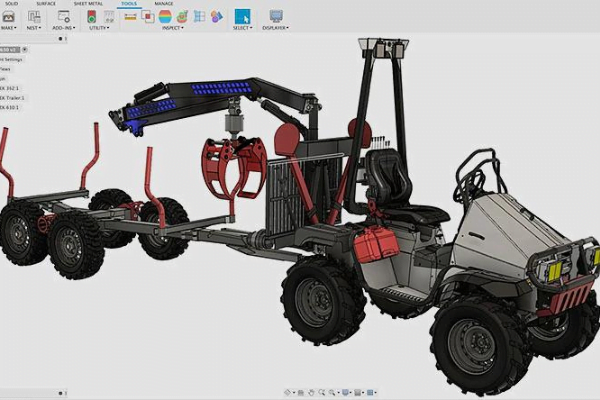
- Single document – Arrange multiple parts together inside the current (single) document.
- Multiple documents – Nest multiple parts together from multiple different document sources.
Nesting:
- Basic arrange – Single-sheet nesting. Arrange multiple objects on a sketch/plane/face.
- Associative updates -Automatically update nests in the event of a design change to any of the nested objects.
- Nest preparation – Access additional settings to control how individual design items are nested (with options to include/ignore elements).
- Advanced arrange* & advanced nesting – Multi-sheet nesting of selected objects. Advanced nesting also provides automatic material, thickness, and quantity detection.
- Advanced part & material controls – Define and override parameters including part quanity, orientation, grain alignment, allowed rotations, cost, and more.
- Process material library – Improve collaboration across your team by building a cloud-based library of sheet stock with commonly used sizes and prices.
- Nest reports – Create custom HTML reports that can be saved and shared in PDF format.
- Nest comparison – Quickly compare nest studies, nests, and sheets with varying parameters to assist with raw material purchasing, quoting, and estimating.
- Part labels – Automatically generate custom part labels that can be affixed to cut parts for easier off-loading and/or tracking.
Product Design Extension
View Features
Manufacture Aware Tools
Plastic Product Design Tools – Define plastic features at the model level or at the assembly level for an optimal approach in maintaining the fit, performance, and aesthetics of your design.
Plastic Product Design Rules – Choose from a list of materials that drive the fundamental parameters of your plastic part design, enabling you to focus more time on your design ideas.
Design Advice – Receive guidance and awareness based on industry best practices and company standards to improve the manufacturability and performance of your design.
3D Modelling
Parametric Modeling – Create history-based features, including extrude, revolve, loft, sweep, etc., that are driven by dimensions and constraints.
Surface Modeling – Create and edit complex parametric surfaces for repairing or designing geometry.
Freeform Modeling – Create complex sub-divisional surfaces with T-splines and edit them with intuitive push-pull gestures.
Direct Modeling – Edit or repair imported geometry from non-native file formats. Make design changes without worrying about time-based features.
Mesh Modeling – Edit and repair imported scans or mesh models, including STL and OBJ files.
Sheet Metal – Design sheet metal components, document flat patterns, and manufacture your design with cutting strategies for water jet, laser and plasma machines.
3D Patterning – Create duplicate faces, features, bodies, or components and arrange them as a rectangular or circular array, or along a specified path.
Geometric Pattern – Apply highly customizable geometric patterns with user-defined or pre-defined objects.
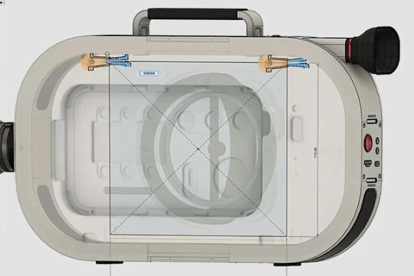
Boss Feature – Create a boss connecting two parts to each other using manufacturing aware tools that are available in Product Design Extension only.
Web Feature – Automate web and rib features from open sketches using manufacturing aware tools that are available in the Product Design Extension only.
Snap Fit – Create multiple parametric snap fit features to fasten bodies or components together.
Manufacture Aware Tools
Plastic Product Design Tools – Define plastic features at the model level or at the assembly level for an optimal approach in maintaining the fit, performance, and aesthetics of your design.
Plastic Product Design Rules – Choose from a list of materials that drive the fundamental parameters of your plastic part design, enabling you to focus more time on your design ideas.
Design Advice – Receive guidance and awareness based on industry best practices and company standards to improve the manufacturability and performance of your design.
Manage Extension
View Features
- Version control
Prepare your model for nesting. Set nesting parameters per material for optimal stock usage.
- Cloud storage
Access your data anywhere. Continue working when not connected to the internet using offline mode.
- Administrative tools
Grant rights to stakeholders inside or outside of your organization with advanced administration tools.
- Commenting and redlining
Capture and share feedback from any device, directly on the design using comments, redlines, and markups.
- User management
Control how users interact with your project data. Manage who your internal and external stakeholders are.
Additive Build Extension
View Features
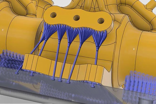
- Enables the creation of toolpaths and support strategies for MPBF additive technologies. Produce metal parts using powder bed fusion machines.
- Access advanced control to automatically orient parts, generated fully associative support structures, and pack parts to optimize the use of the build space.
- Select 3D print parameters -Select from the most popular metal additive 3D printers to configure Fusion 360’s Manufacture workspace for your process.
- Orient parts – Identify the ideal orientation for your parts to minimize support material while achieving the best surface quality and a successful print.
- Associative design & manufacturing data – Connect your design data to manufacturing seamlessly. Set up manufacturing once and let Fusion 360 update as needed when you change the design.
Who uses Fusion 360
3D CAD/CAM for machinists
Machine quality parts faster. Reduce cycle times to improve the bottom line.
Design systems for collaborators
Smart tools let you connect extended teams in real-time.
3D modeling for mechanical engineers
Process controls to design, simulate, and manufacture all in one program.
3D PCB design for electronics engineers
Unify schematic, PCB, libraries, simulation, and mechanical design.
3D prototyping for industrial designers
Speed up ideation and connect with engineering teams faster.
A modern 3D platform for educators
Prep students for careers in design, engineering, and manufacturing.